
Just Build It

Wentao Zhong
The circle grows up. It becomes a node.
The Joint
Chapter 01
Anyone can make a panel. The patent is the ball — one node that lets any unit connect, come apart, and recompose.
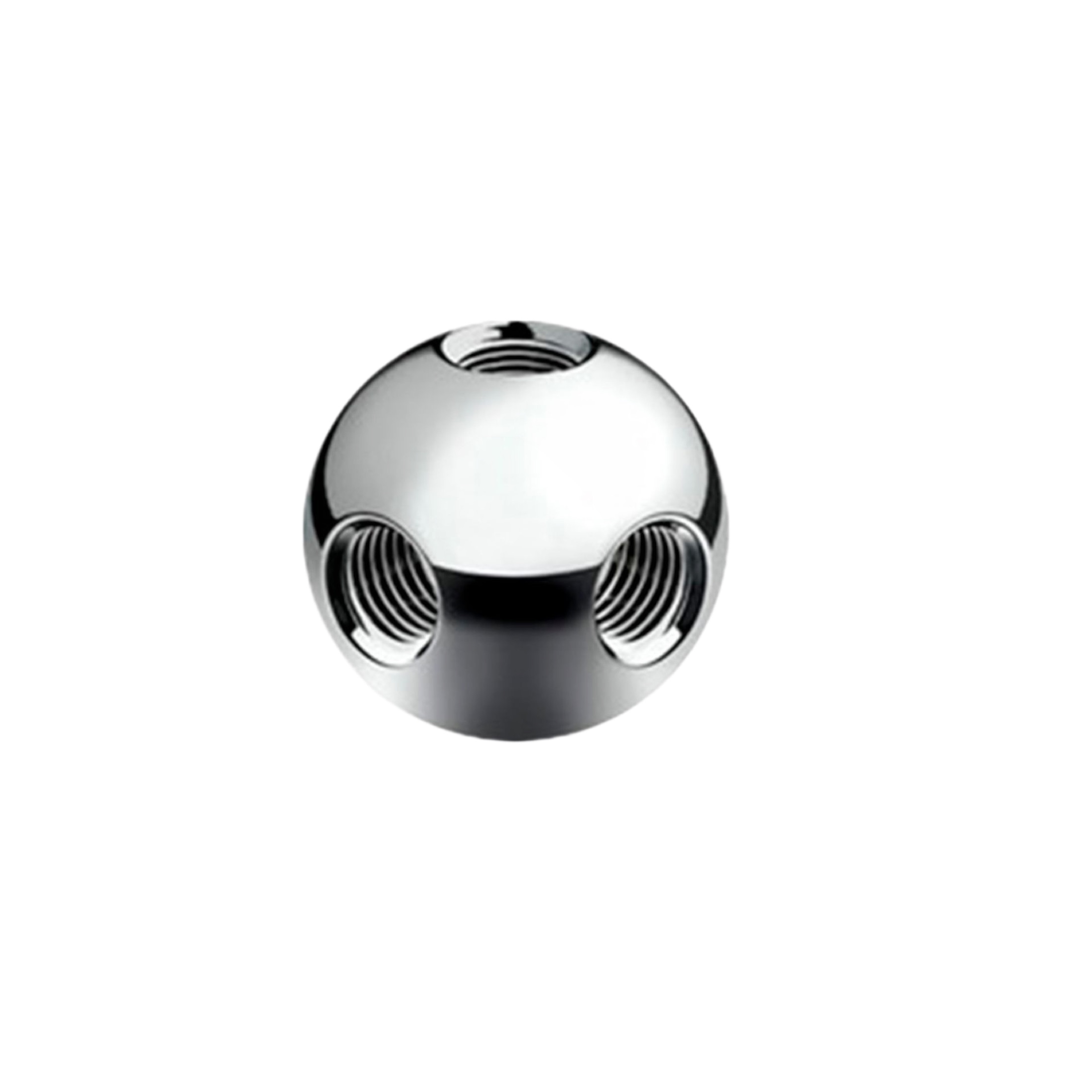
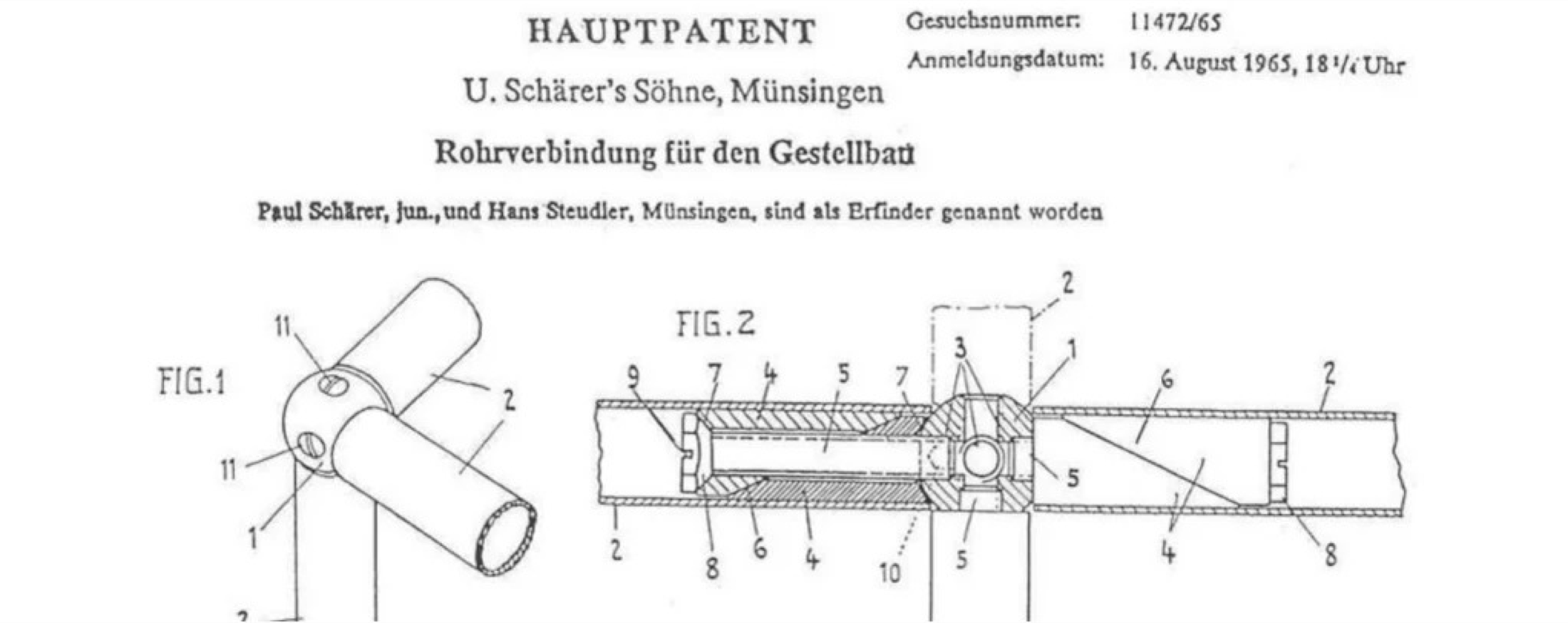
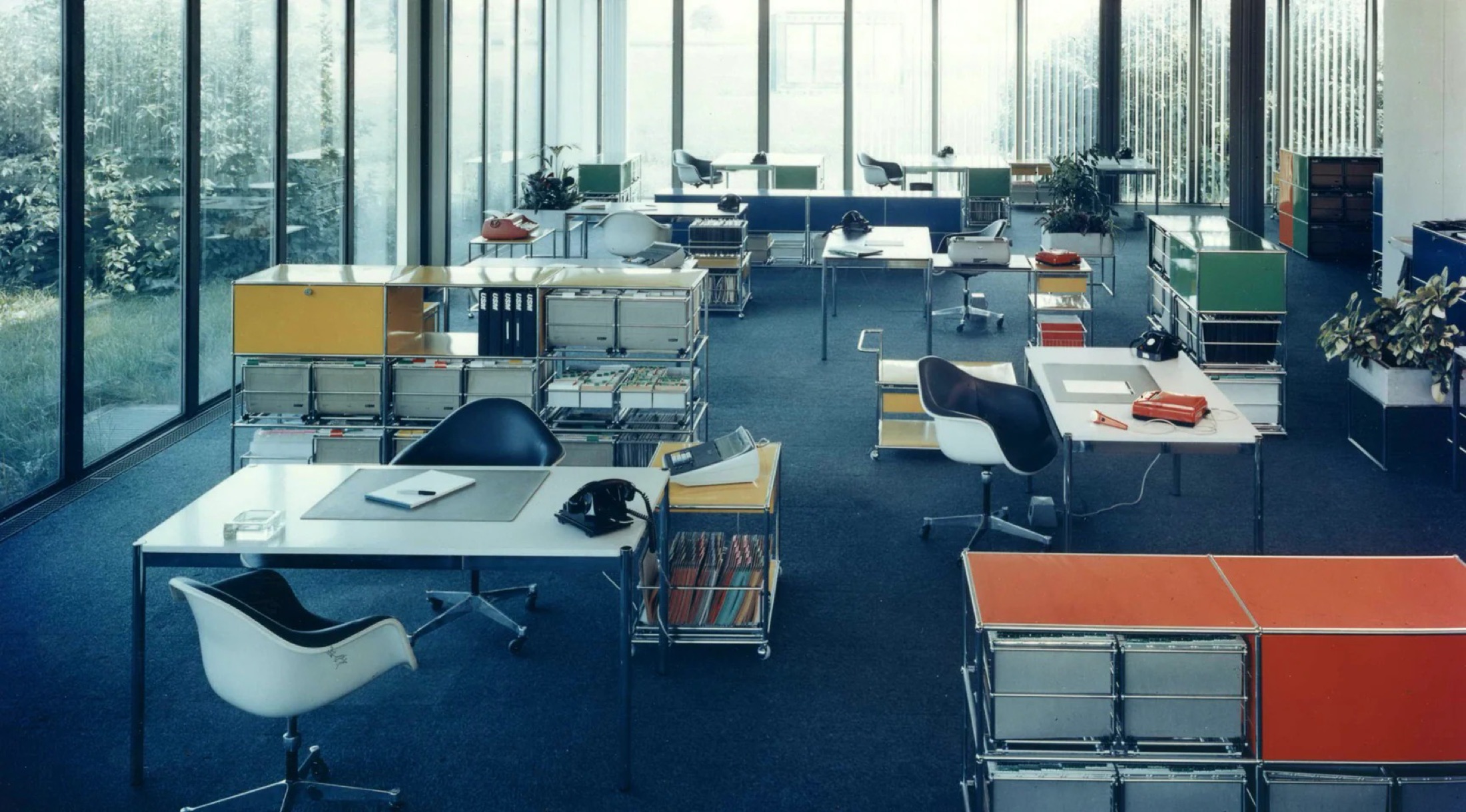
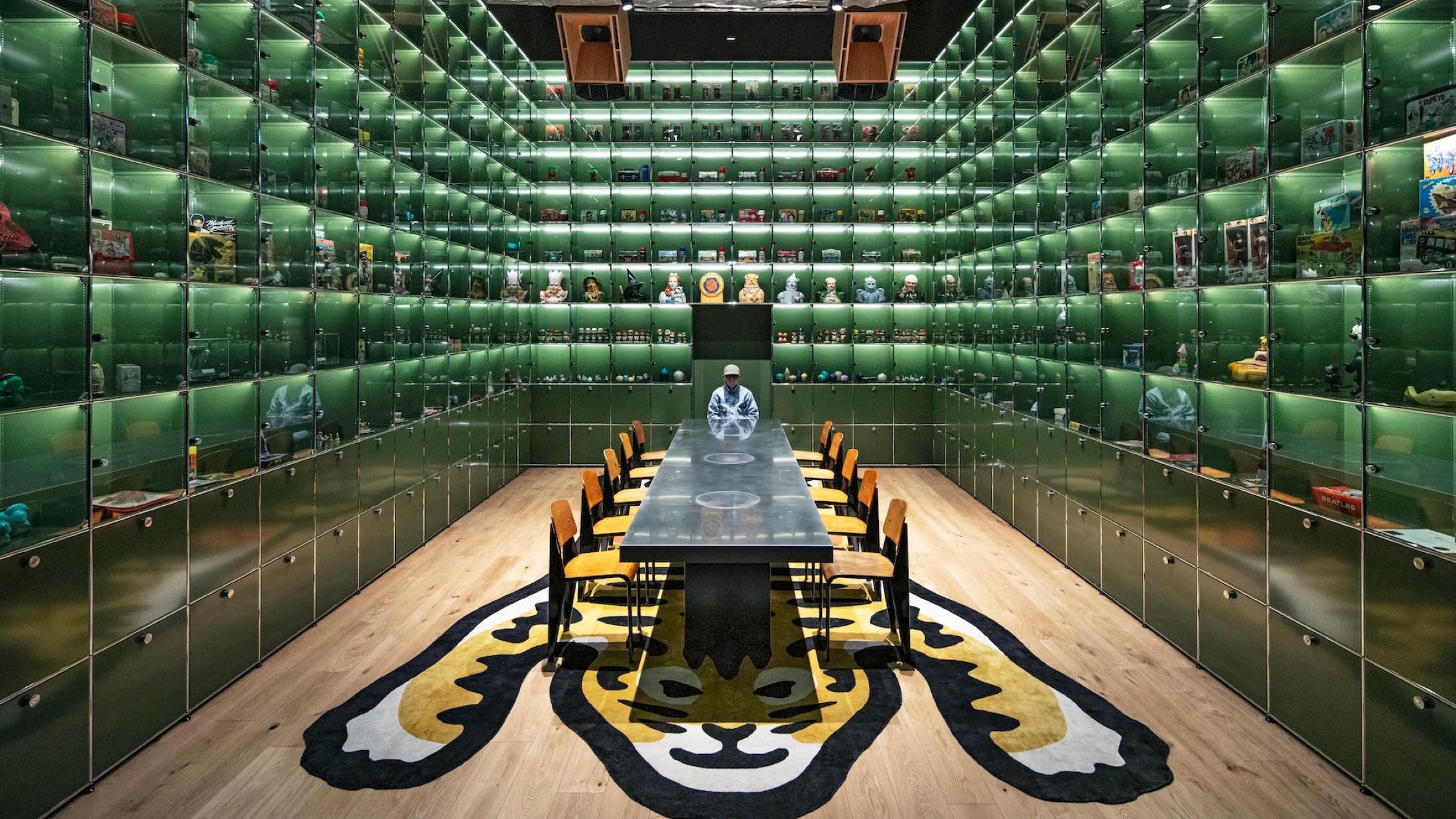
The atomic unit · Patent drawing · An open system · With enough imagination, it becomes a wall.
The Original
One Circle.
Chapter 02
Every design I make starts the same way: find the smallest unit that still holds the whole idea.
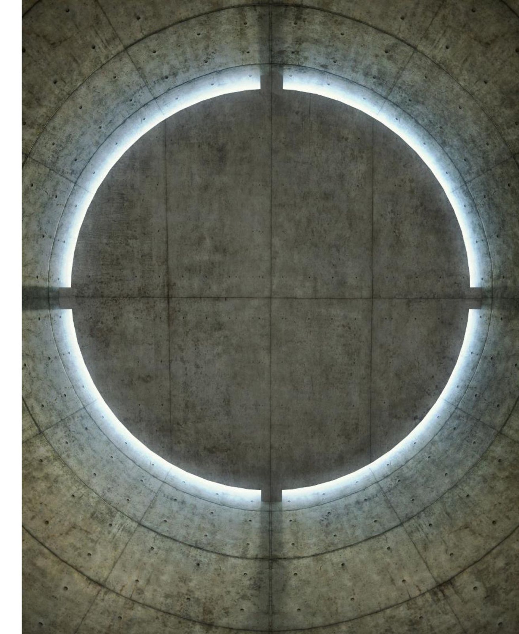
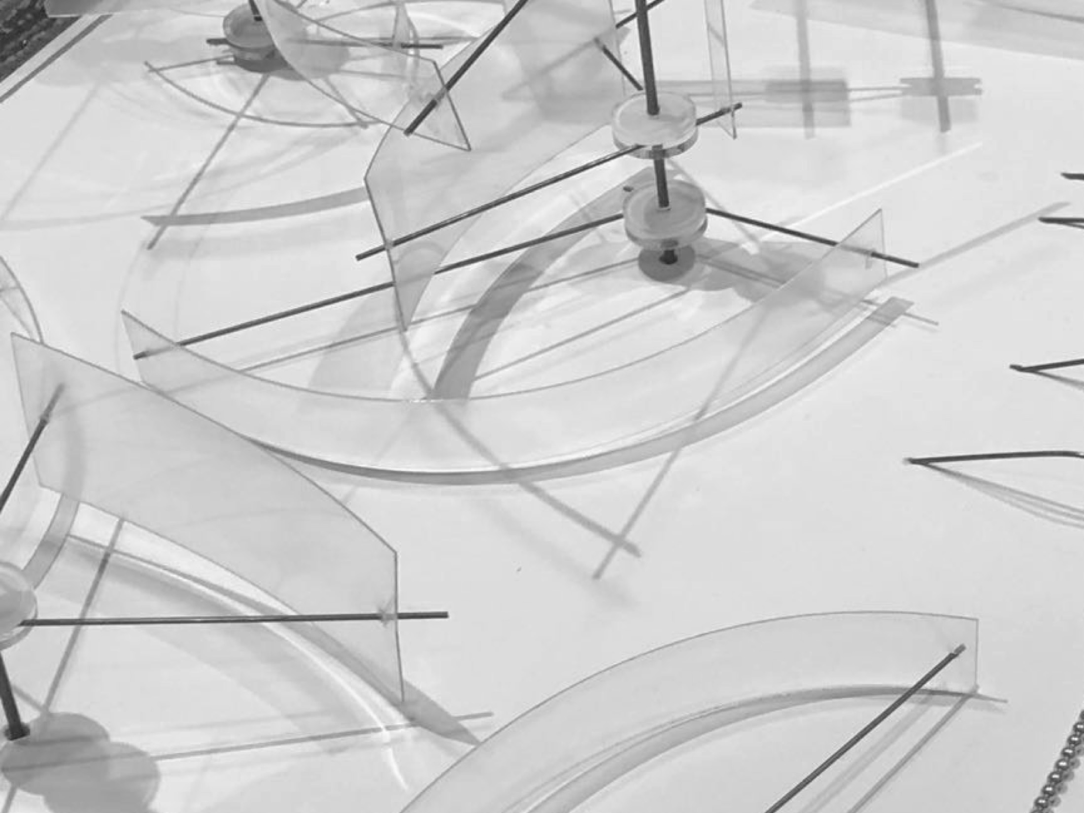
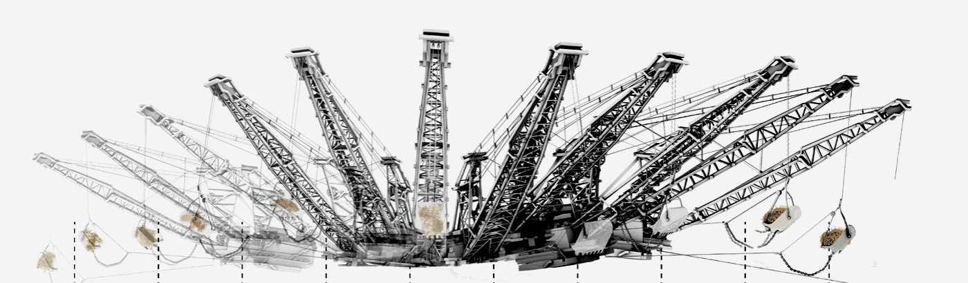
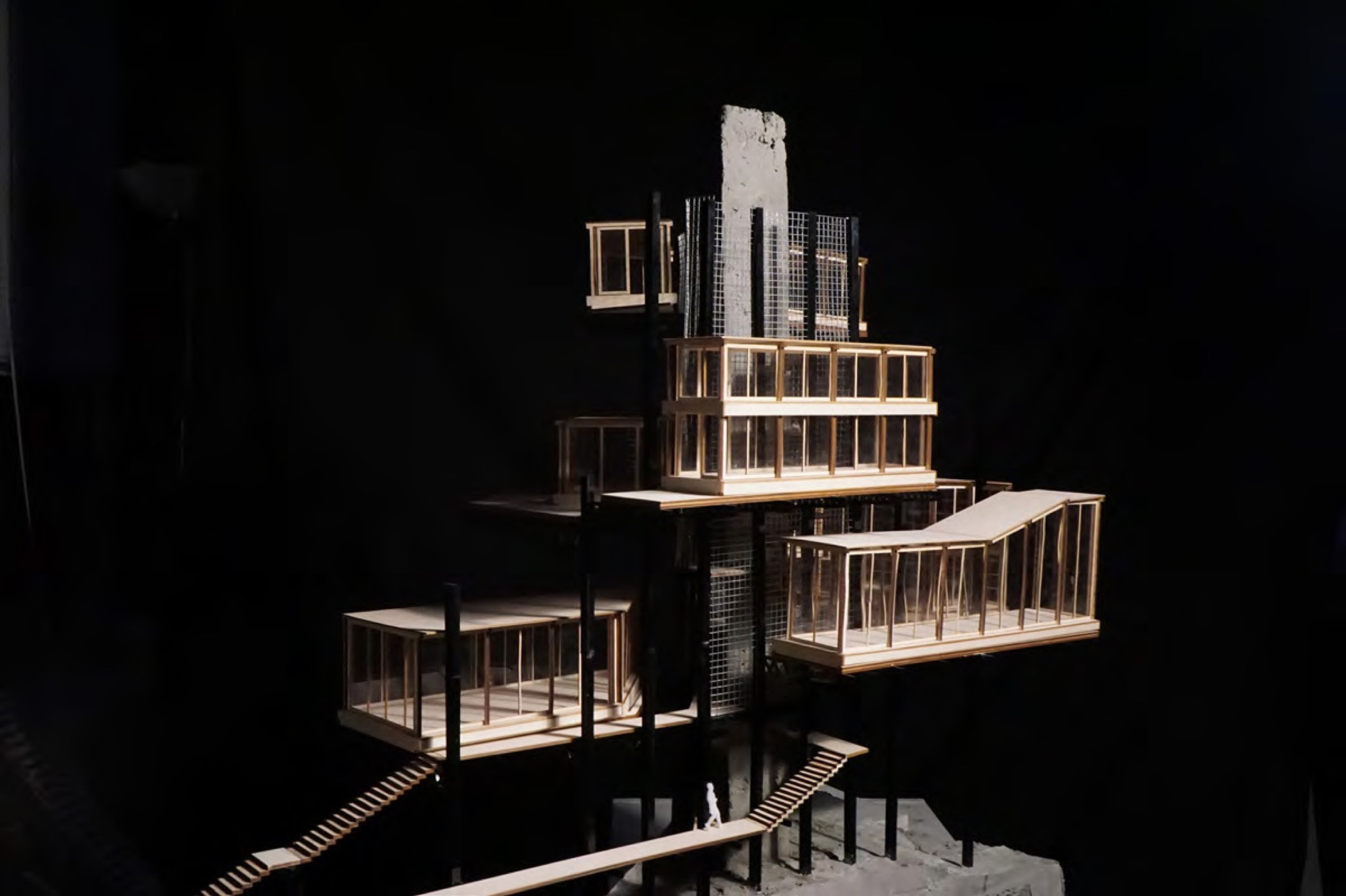
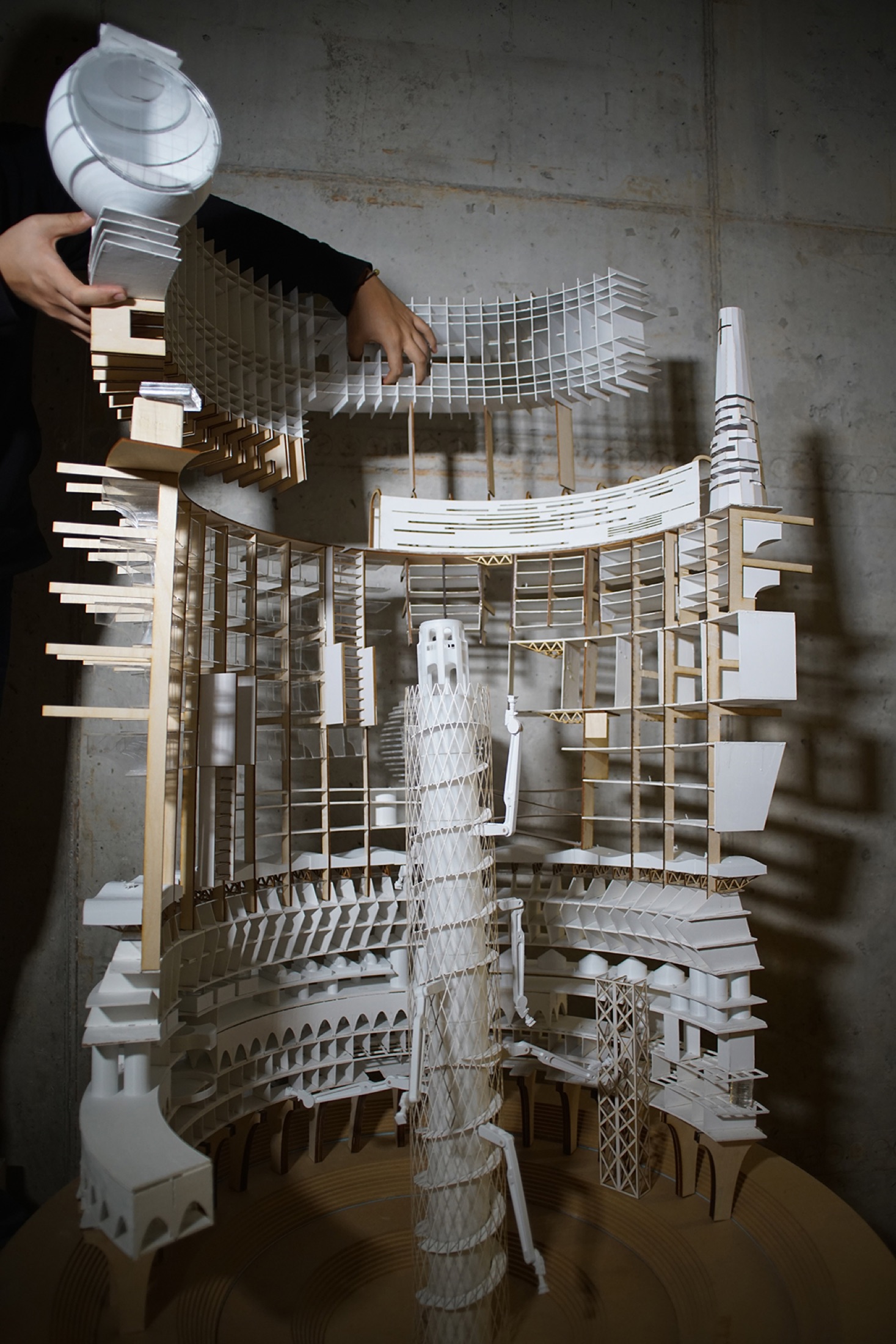
Tadao Ando · UNESCO Meditation Space — then broken (On Goldness, SF) · traced (Page 625 walking dragline) · stacked (Tower model)
Same circle, read as an atom — then built.
So I Built It.
Chapter 03
I stopped designing the object and designed the forces between the players — one person's weight is another person's lift.
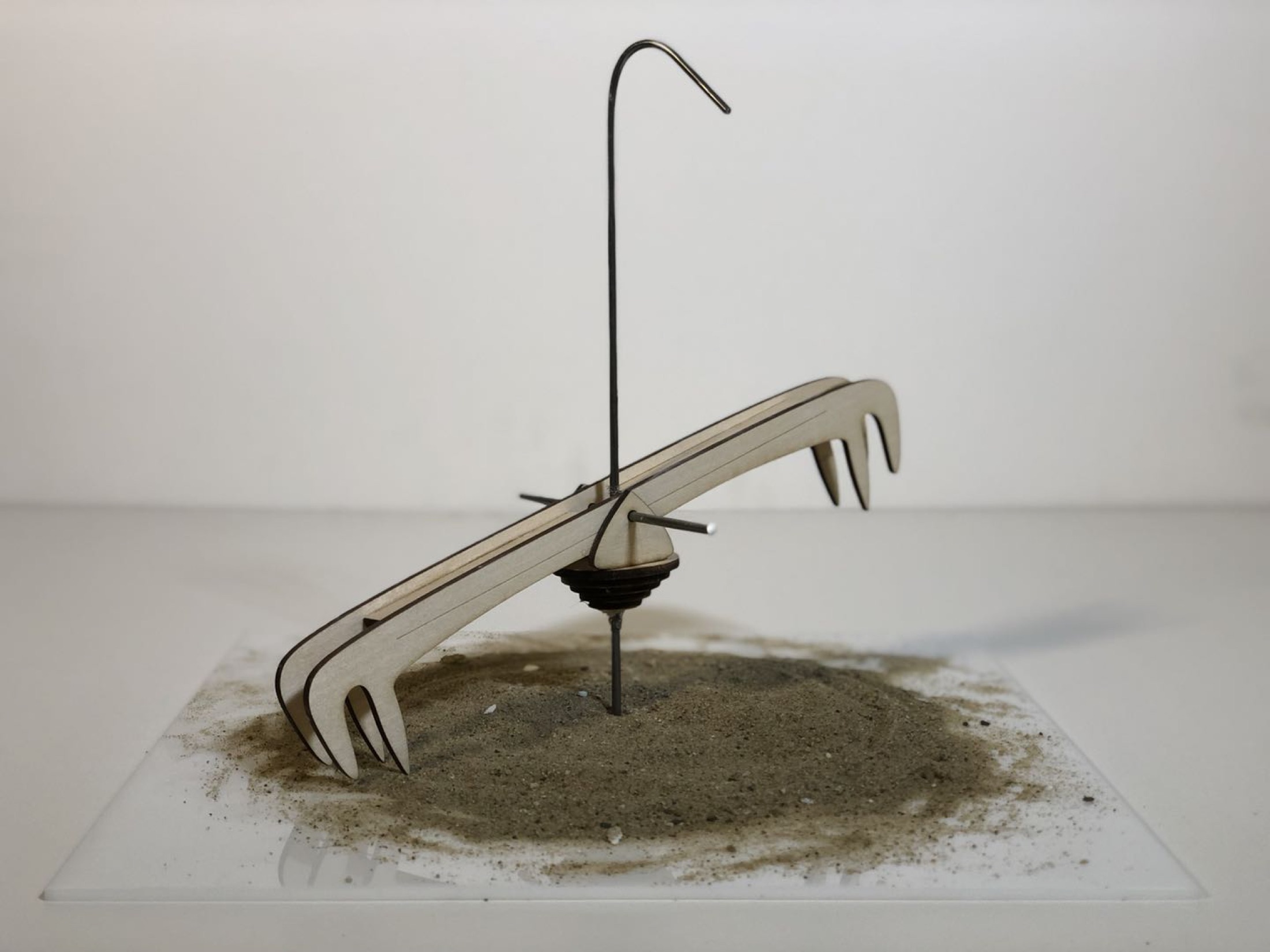
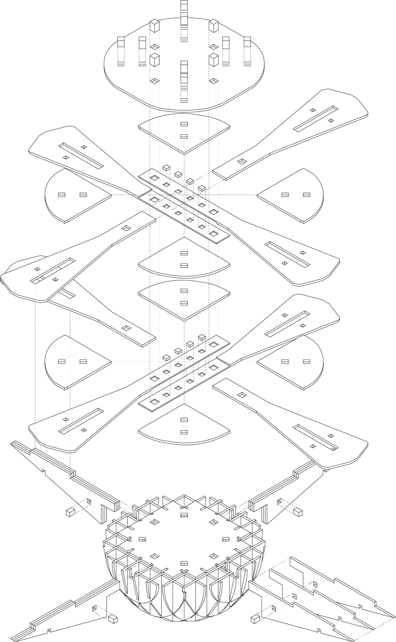
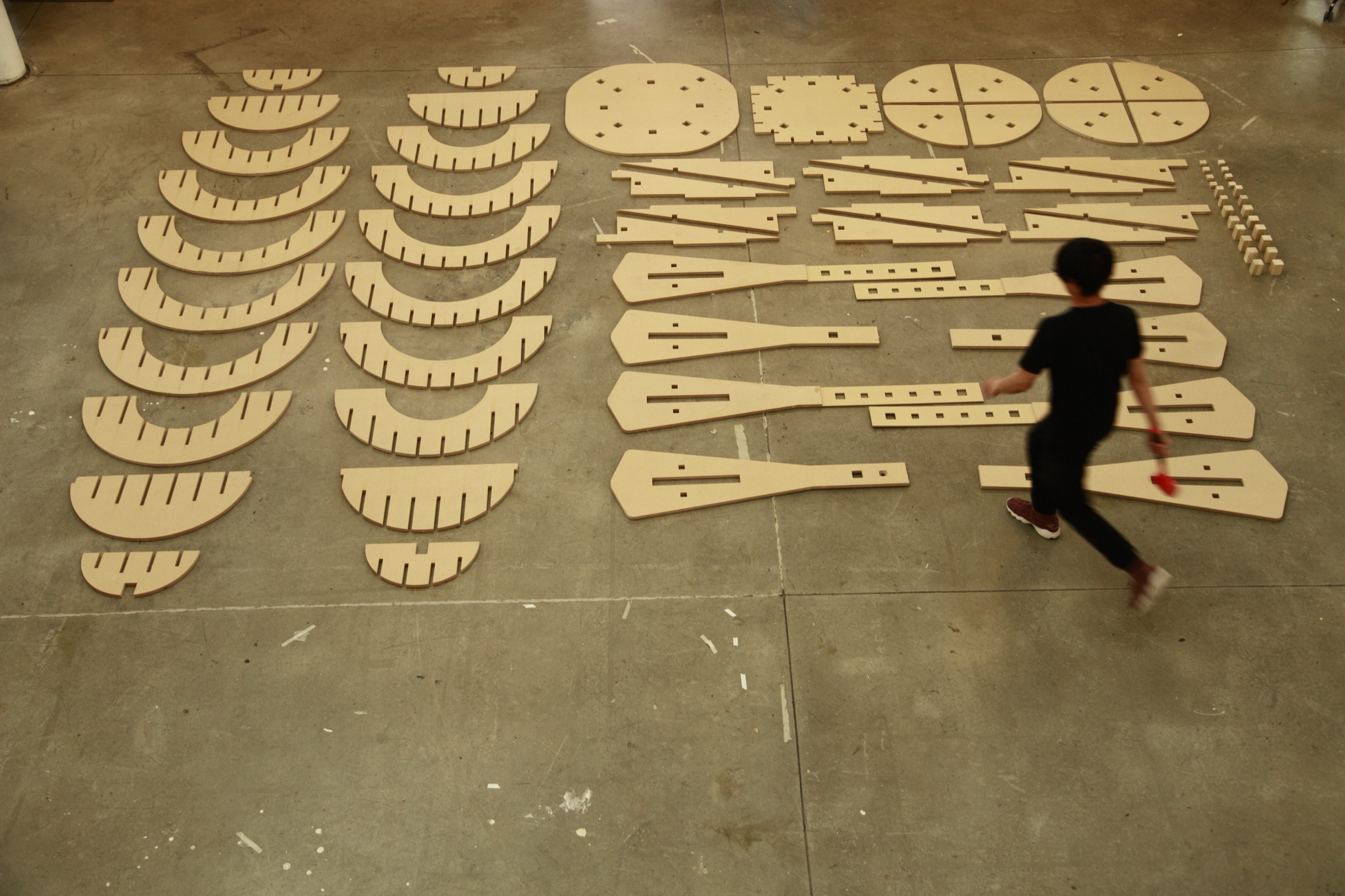
Toy! · Fun / Danger / Gravity · Fabricated parts · Played — four players
Same grammar, city scale.
The Unit Changes. The Joints Don't.
Chapter 04
One park at the center of three cut-off communities, after Hurricane María. I didn't design the city — I designed the node.
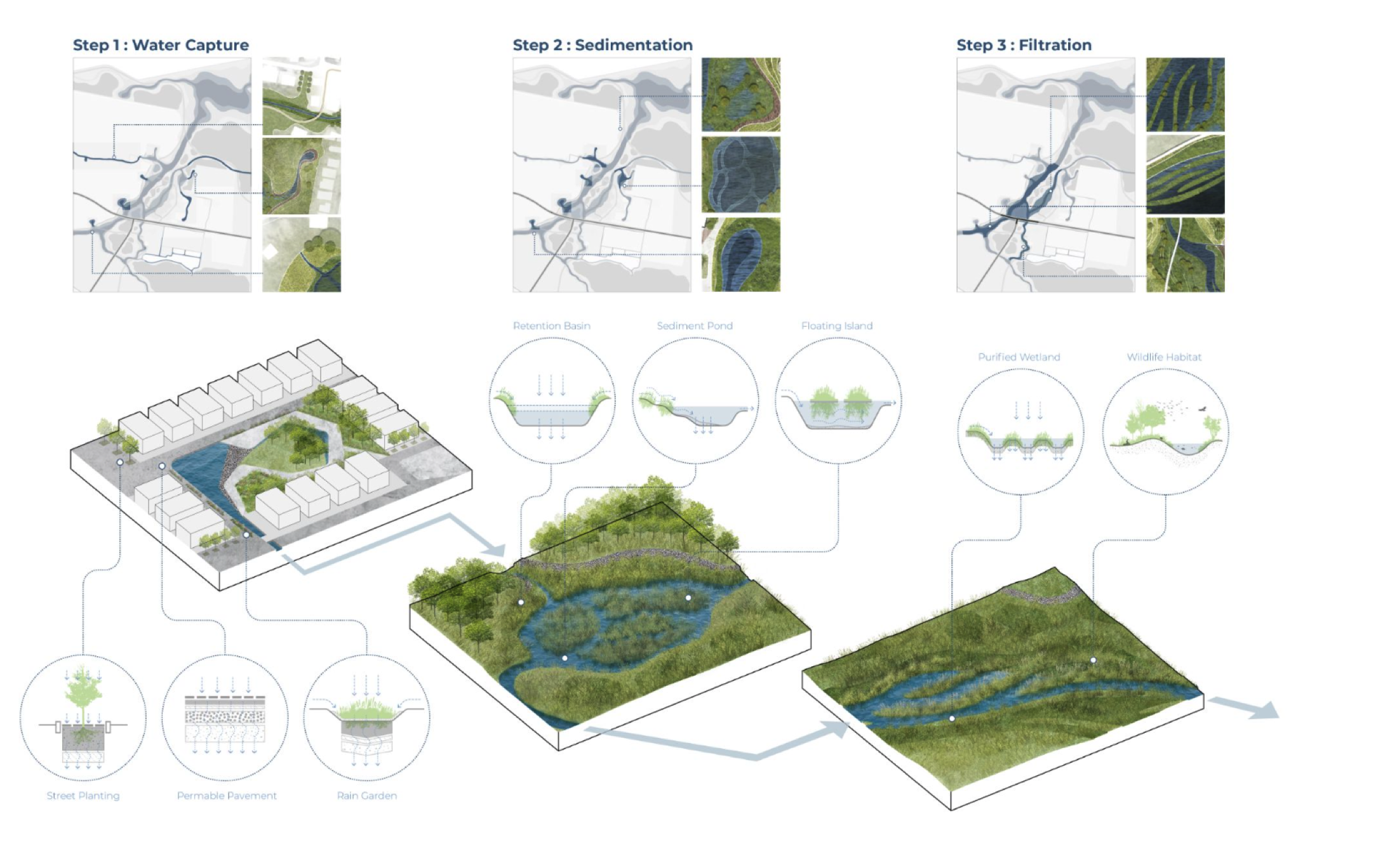
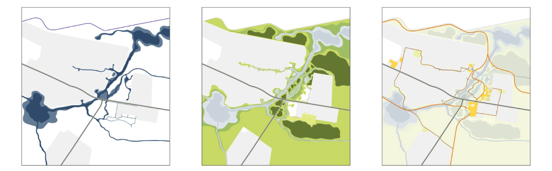
Toa Baja Central Park · Modify topography / Improve ecosystems / Revitalize & protect communities
Four chapters. One designer.
As a designer, I design mechanisms, not objects.
Organism, software, hardware — everything runs on something. My instinct is to find that something, abstract it into a node, then go find the problem it was waiting for. The connection between them is the design. It always has been — that’s what the last four chapters were.
But before I abstract anything, I live with it. I organize, I watch — how people gather, work, waste time, fall in love with objects. A mechanism you haven't lived through is just a diagram. Beauty comes from the difference.
So I watched how my designer friends spend their weeks — and how I spent mine.
Where does a designer's week actually go?
What gets drawn twice, translated three times, rebuilt from scratch?
And how much of it is actually design?
A composite scene — public designer interviews plus my own production years. I went looking for the mechanism, wrote it as my brief, and built everything after this page to answer it. Validation belongs with real Nike designers — week one.
Designer
Honestly, most of my week isn't design. It's production.
Wentao
What does that look like?
Designer
One direction gets approved — then thirty colorway variants by Friday. Same shoe, redrawn again and again.
Feedback comes from everywhere — Slack, email, meeting notes. Half my time is translating comments into what to actually change.
And when we go 3D, I rebuild the concept from scratch.
Wentao
If those disappeared, what would you do with the time?
Designer
Design. Explore more directions earlier. The thinking part.
Need → Output
Remove the mechanical.
Expand the possible.
Keep the judgment.
The Missing Layer.
City, building, landscape, furniture, interface — I ran one grammar at five scales. When I looked at AI, I didn't see a tool. I saw the sixth: a layer nobody sells, between the models anyone can buy and the way designers actually work.
intent · constraints · state · evaluation · handoff — models change; this layer is the durable system.
- Track 01Model
- Track 02Orchestration — the missing layer
- Track 03Interface
Working now
So I built it — again.
From design intent to controlled exploration, review, and handoff — a working prototype built in days, not a speculative vision of AI for footwear. I wanted to build enough of it to make the conversation real.
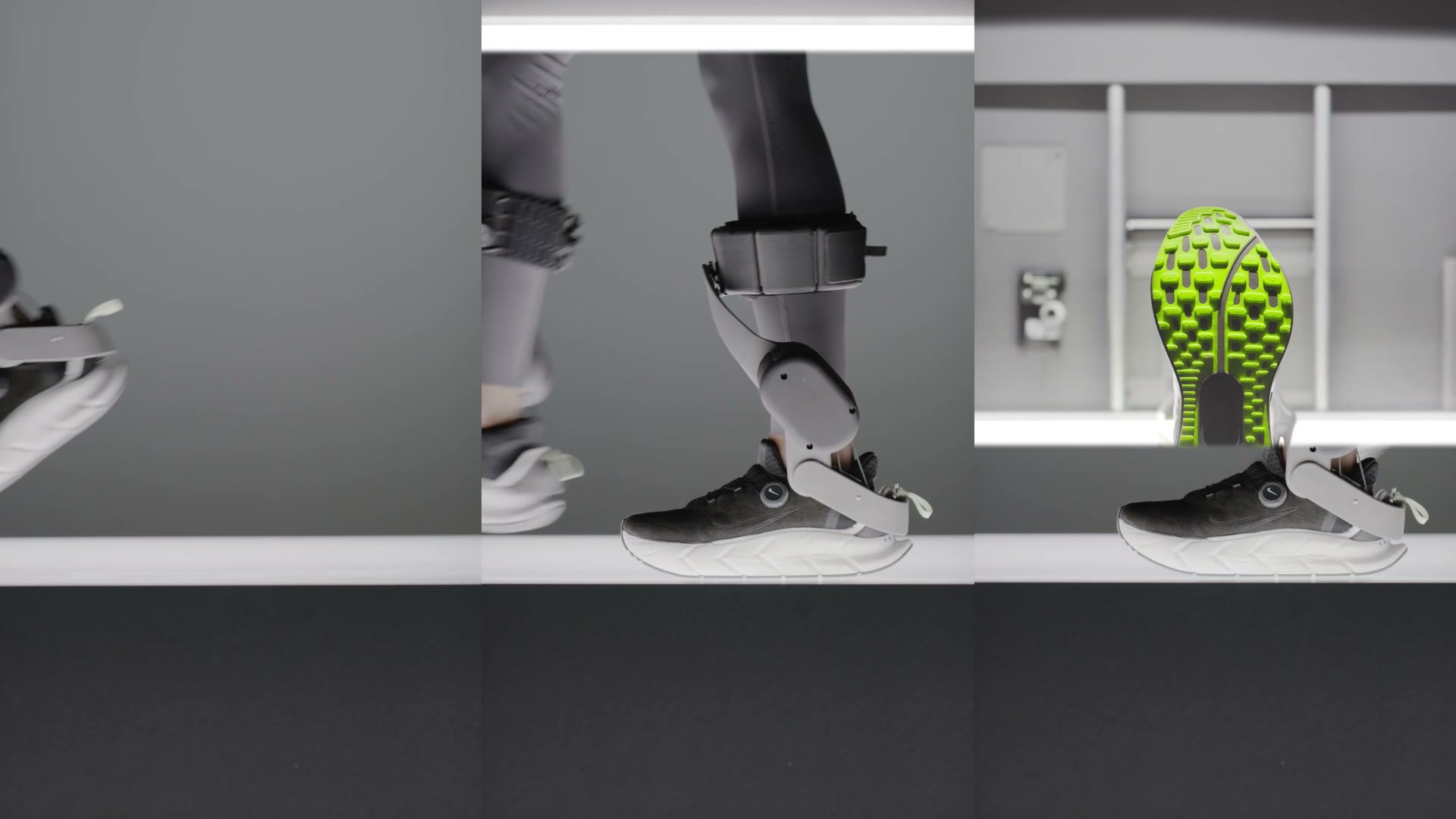
Designers are the center
The designer is the athlete.
AI is the training system.
At Nike, the athlete is the hero and the product is equipment. Same rule here: I'm not building an autonomous designer. Each tool removes one bounded mechanical step — and the designer decides when to use it.
Autonomous super-agent
- Chooses and executes the full path
- Hides intermediate decisions
- Generalizes taste
- Optimizes for completion
Specialist studio tools
- Supports one bounded design task
- Produces reviewable artifacts
- Preserves each designer's taste and intent
- Optimizes for authorship and control
One big agent optimizes for automation. Specialist agents preserve authorship.
The shoe is already a USM.
One silhouette, hundreds of colorways — the AJ1 has been recomposed for four decades, and Nike By You hands the panels to the customer. Structure fixed, panels open. I'm not importing a system. I'm making the one you already have computable.
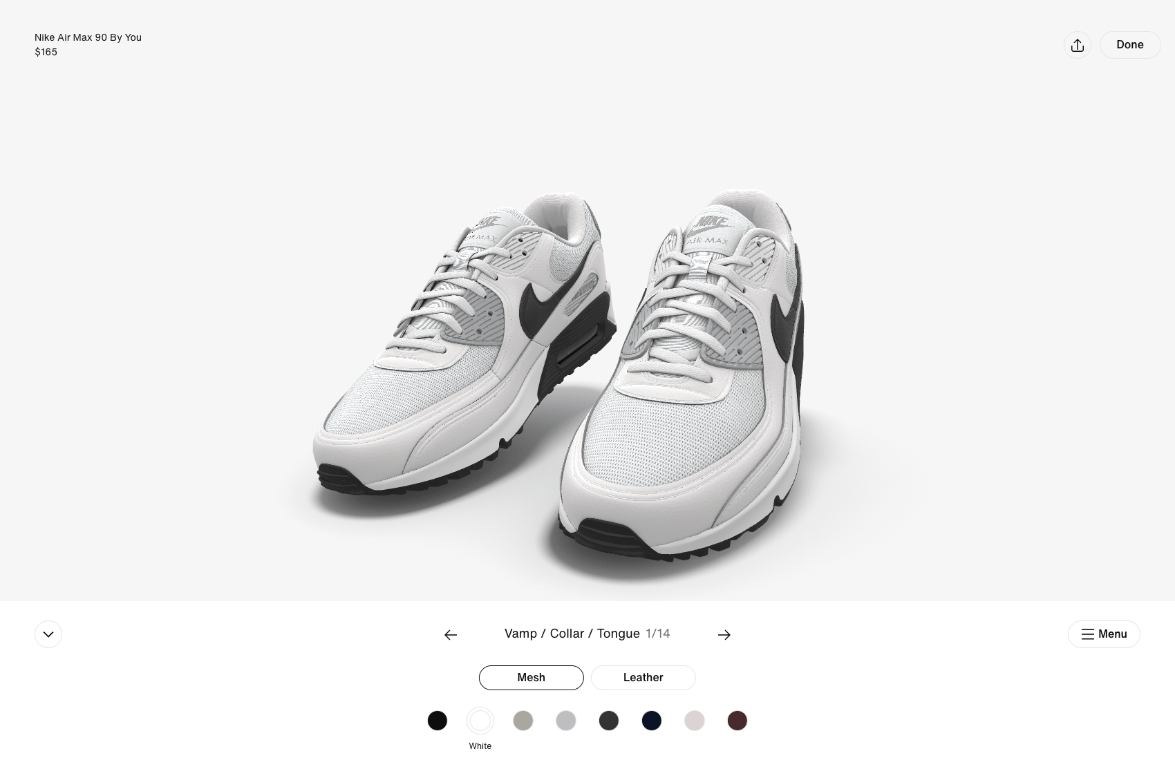
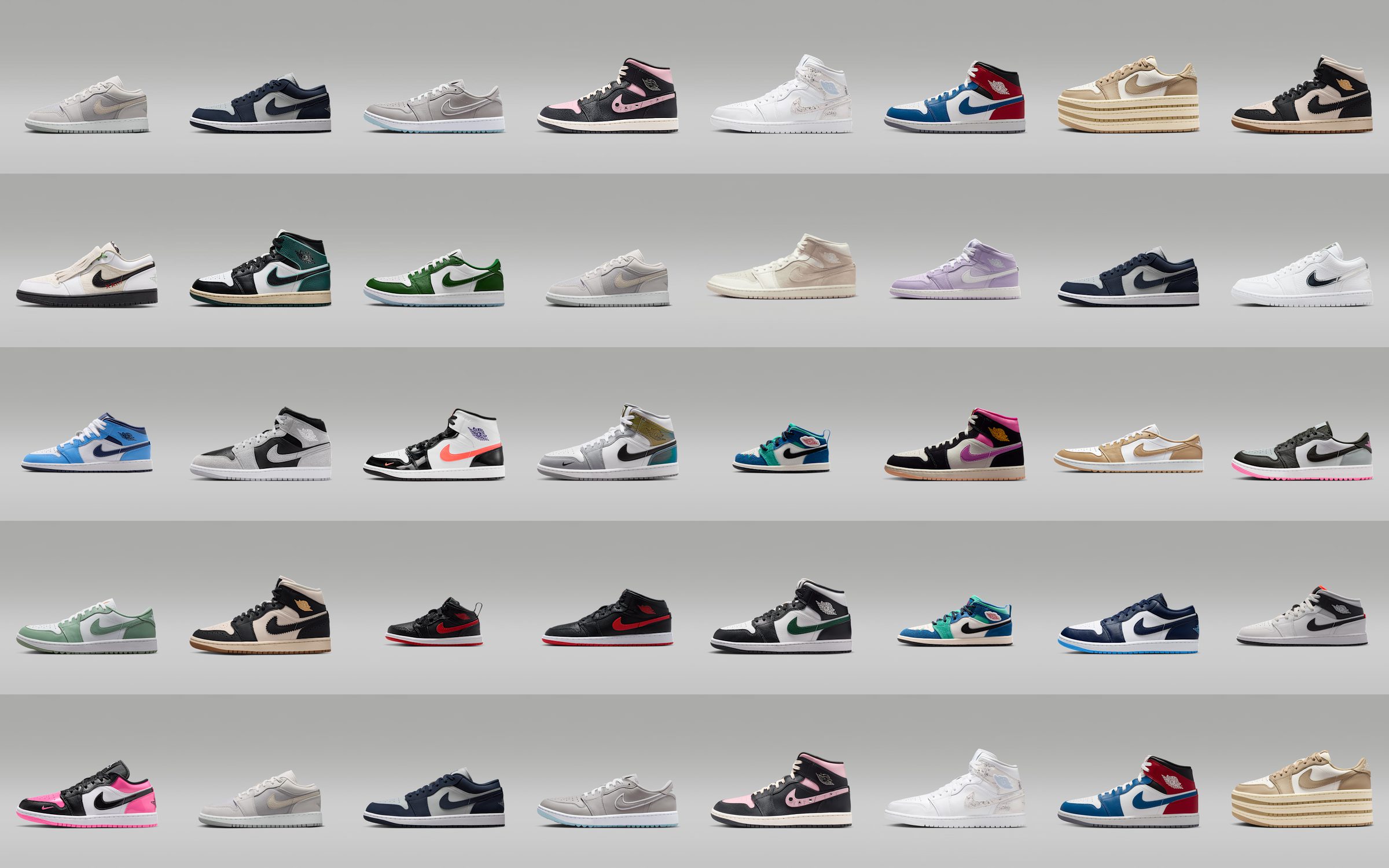
Locked regions = structure. Flexible regions = panels.
Working proof
Does it actually work?
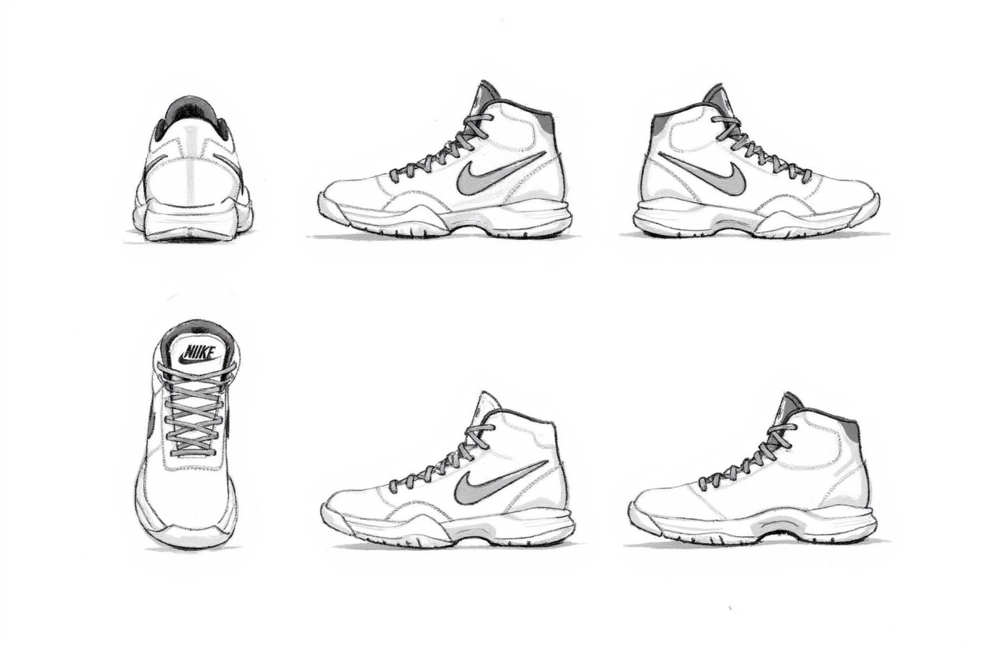
Sketch → Six-view → SAM3 layers → Colorway batch → Human review
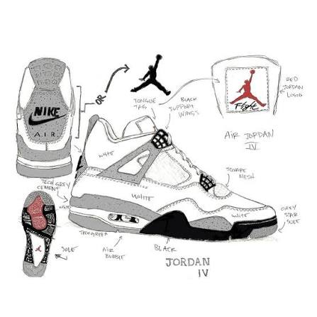
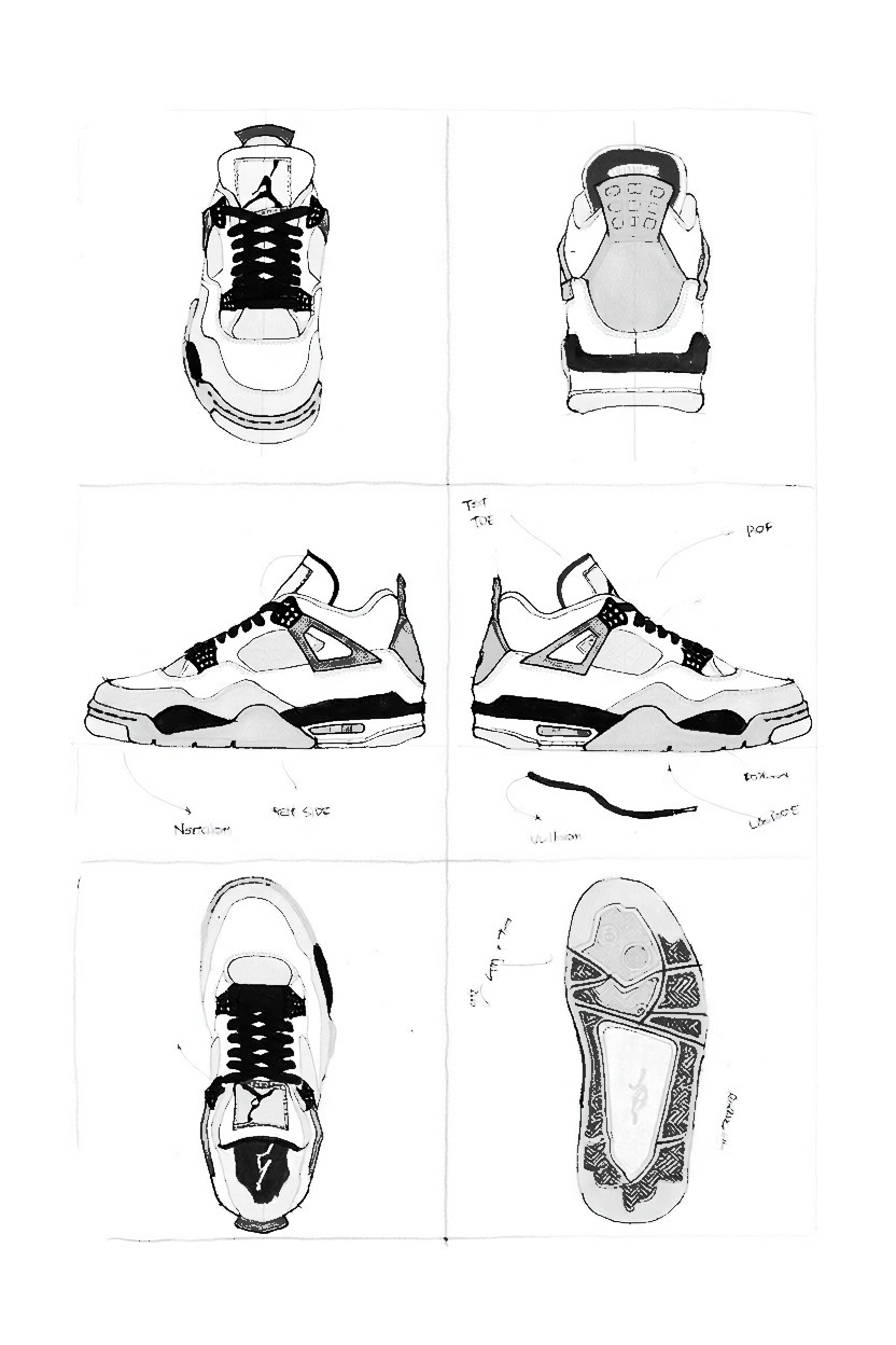
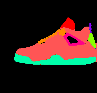
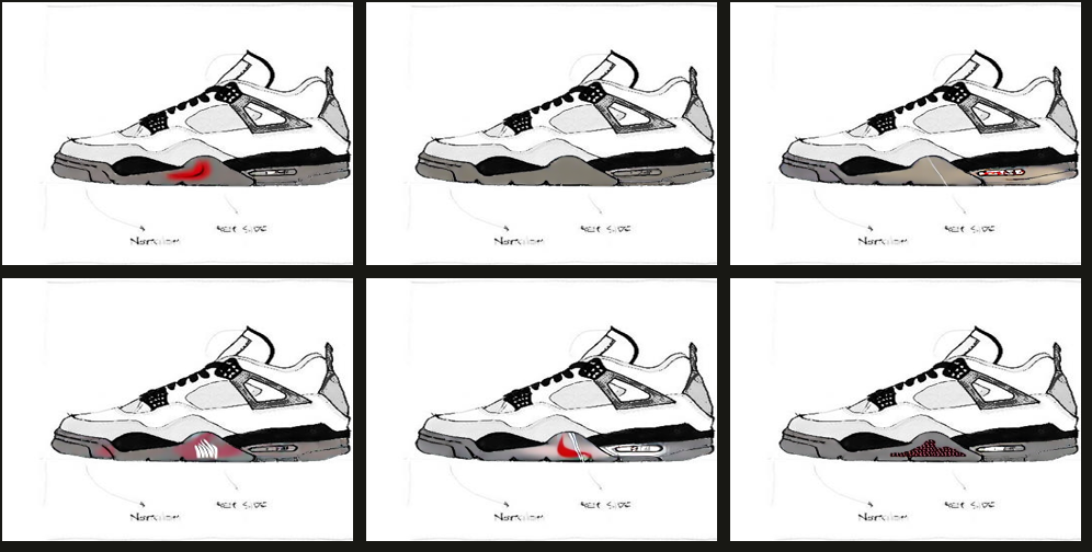
Live region lock on real masks · scripted walkthrough from real pipeline outputs — no live calls on stage.
Where a decision got better
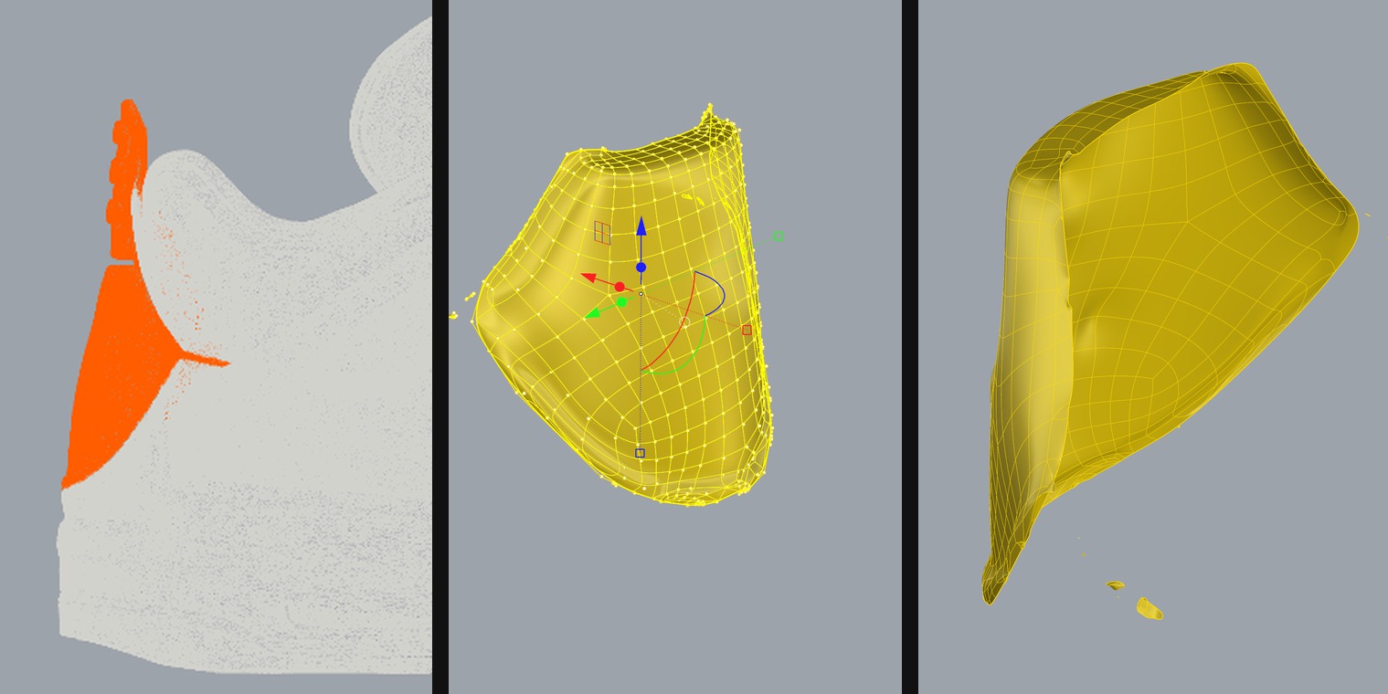
The concept mesh made the heel read bulky within thirty seconds of the proportion gate. Twelve minutes of SubD cage editing fixed the volume the same morning — a direction call made at concept speed, before a week of remodeling got spent on the wrong heel.
One documented run — the 3D fork page, two ahead, carries the detail.
One connected studio, led by the designer
Working now — 2D pipeline: sketch → six-view → part layers → controlled batches → review → render. 3D branch: approved views → concept mesh.
Supporting — Design Intent structures the brief and locks regions before generation.
Roadmap — Feedback-to-Action and Project Graph carry review decisions forward.
New capability — for the Nike Archives
The archive has no source files.
The Department of Nike Archives keeps hundreds of thousands of artifacts — catalog pages, ads, product photographs. The film and the PSDs are long gone; every artifact is one flat image. When a team mines the archive for a re-release, reusing heritage means re-shooting or repainting. Layers turns the flat artifact back into named, editable layers — the archive becomes workable design material again.
Department of Nike Archives · hundreds of thousands of artifacts · collection from the 1970s · department est. 2006
Image
One approved hero frame on the canvas.
Layerize
Seedream · RGBA cutouts + z-order.
Layer nodes + panel
Each layer lands as a node; the Layer Panel holds the stack.
Per-layer verbs
Remove BG · Draw-to-Edit · Gen-Fill — one layer at a time.
Recompose
The stack flattens back only on approval.
Edit the part, not the picture.
Decomposition is automatic; every layer is a real node on the canvas with its own name, z-order and bounds. Nothing is merged until the designer says so.
Offline scripted demo · pre-baked outputs
The 3D fork
3D is not one thing.
Each representation is only useful for a specific design decision. The fork carries an approved 2D design state through four of them.
Visual 3D · multi-view · turntable
Does the design identity survive rotation?
Working — F06 probe · F09 sweep
Concept mesh · rough AI geometry
Does the volume work? A confident reject in thirty seconds is a success.
Working — approved views → mesh, double human gate
SubD / NURBS · Rhino
Can the designer correct the spatial hypothesis — and what does that labor cost, in minutes?
One documented run — heel region, QuadRemesh → SubD → designer edit
Last · patterns · tooling
Real footwear CAD takes over. My tool stops here — deliberately.
Handoff package, not a claim
Physical sample
The loop closes in the designer's hands.
The point of all of it
A mesh you cannot edit is disposable. Price it that way.
The decision from the proof page, priced in labor: 121k triangles → editable SubD in 5 seconds of compute; the designer's twelve minutes were all judgment, zero mesh repair. The labor did not disappear at conversion — it moved to where it belongs.
Before I trusted any of it —
Where does a generative system stop being useful to a designer?
The whole pipeline, run
Nine workflows. I ran all of them.
This is one system, run end to end — model × workflow × task × controls × reference policy. The instrument on the next page is what puts a system like this one beside another and refuses to tell the designer which is which.
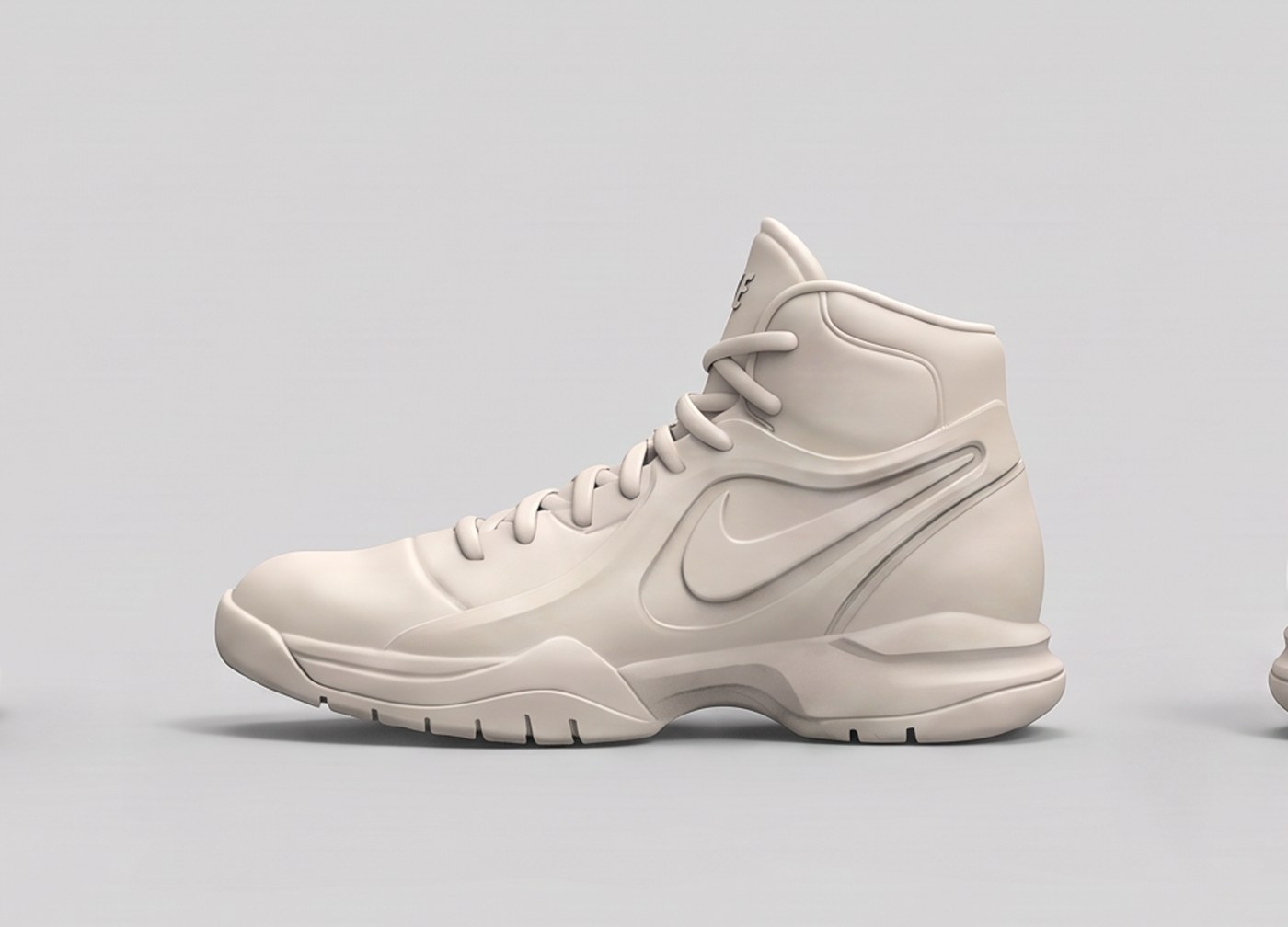
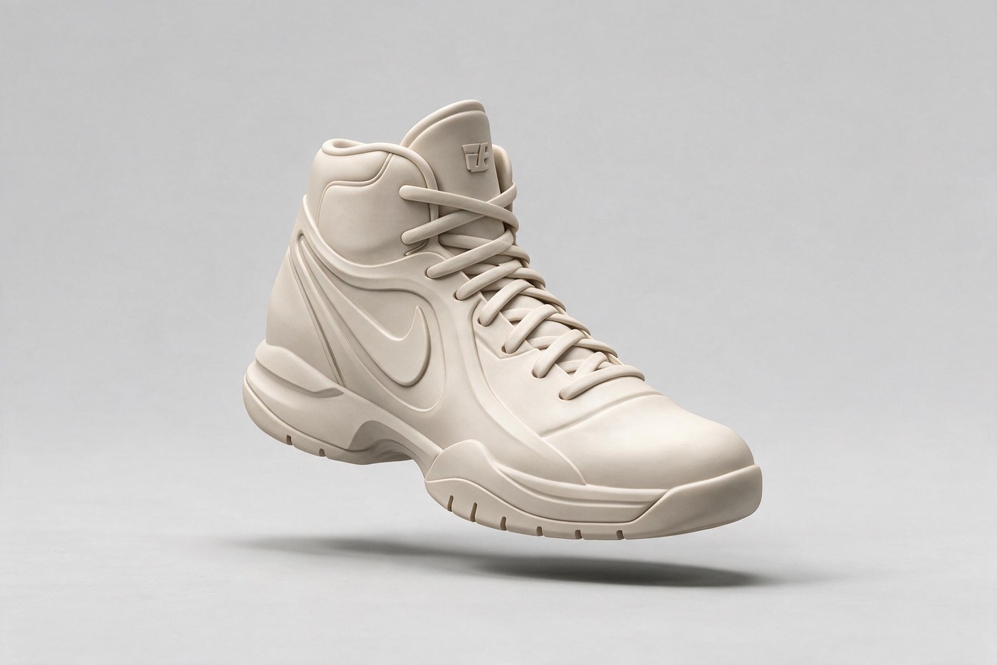
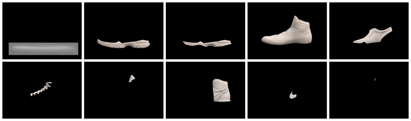
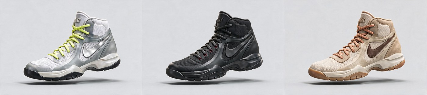
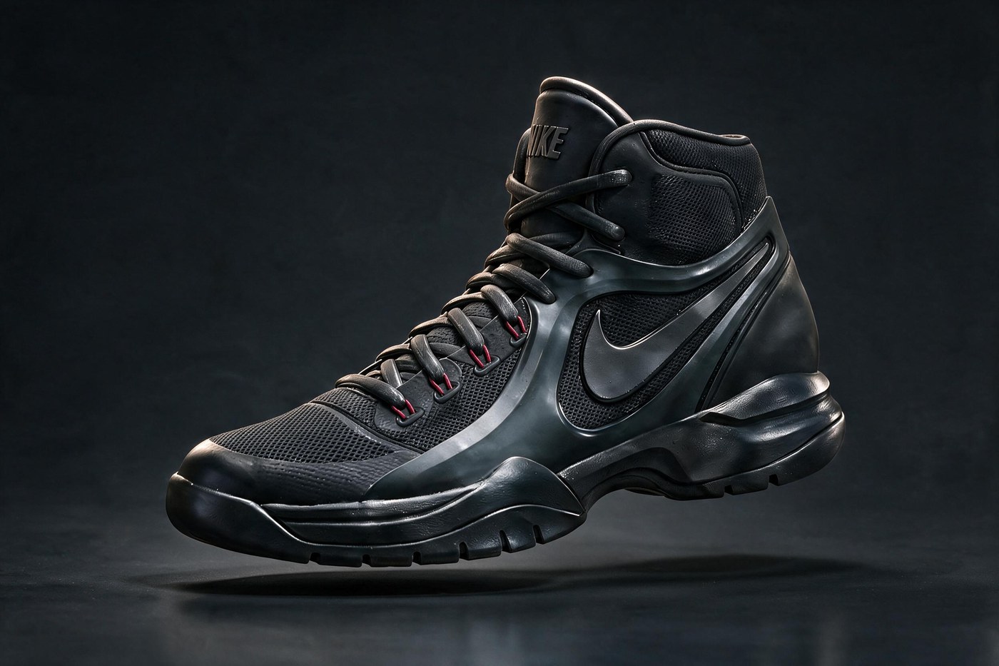
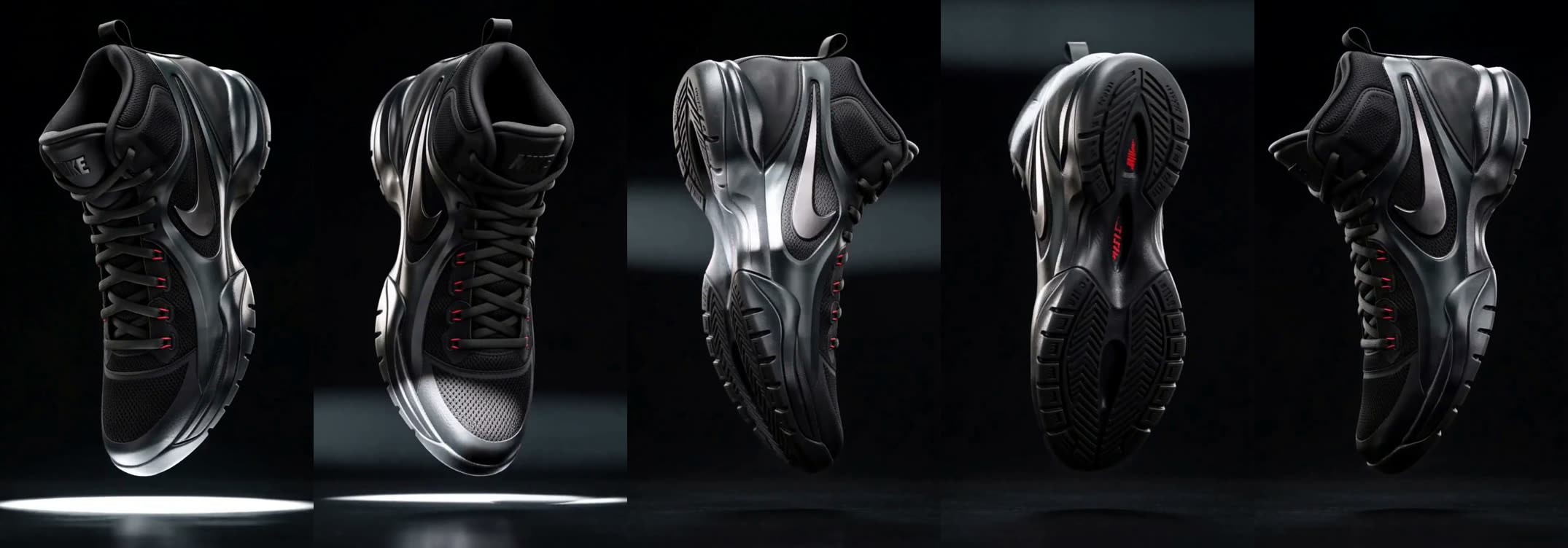
The approved design suspended and turned while one light sweeps up from the floor — outsole, then sidewall, then upper. Five seconds, generated from the F07 hero and the F06 view set.
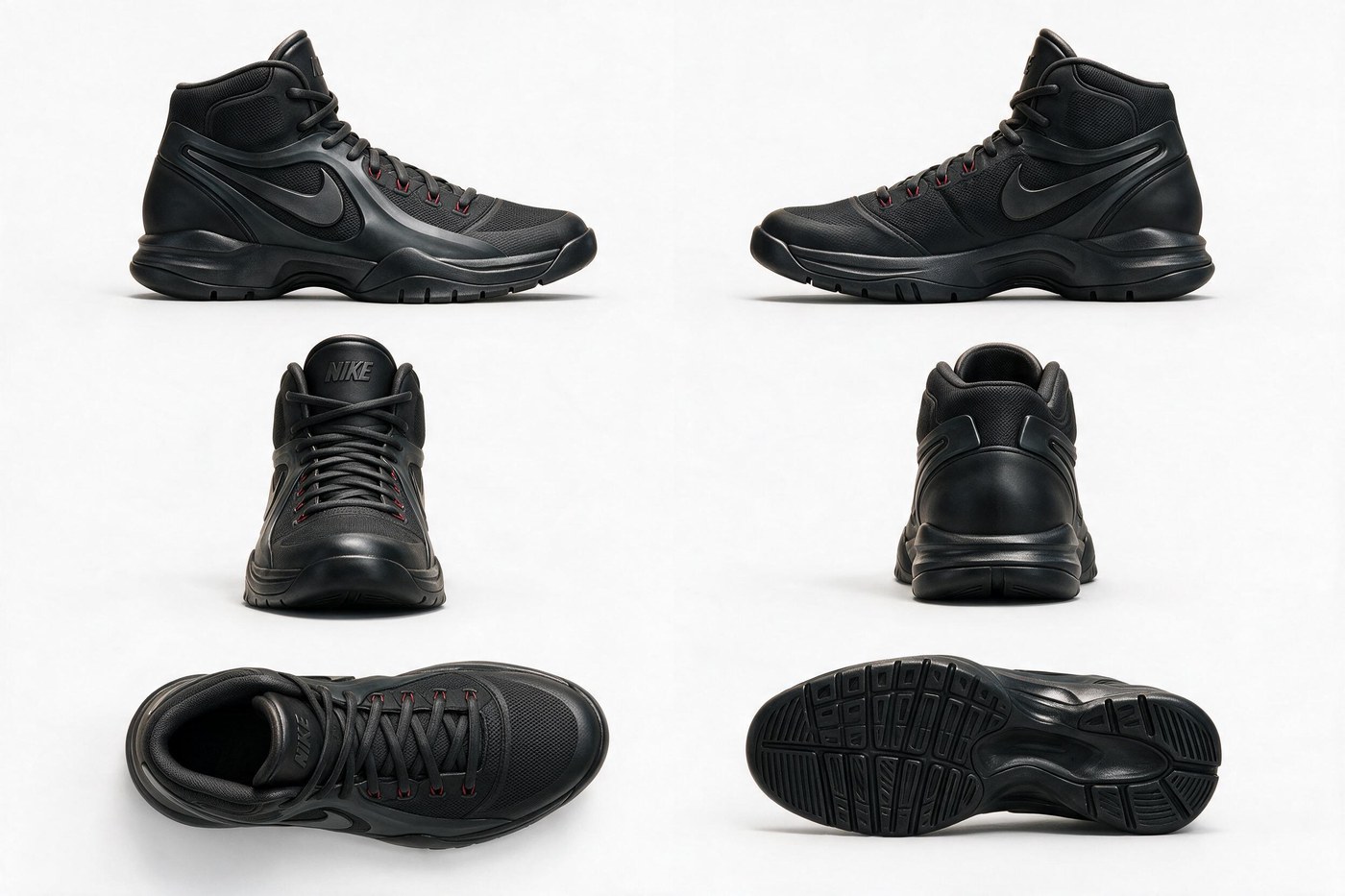
The last stage of the pipeline is the only one a still cannot argue. Either the identity survives the rotation or it does not, and you can see which within a second.
34 portable .api.json / .workflow.json files — drag any one straight into ComfyUI.
Repeatable, or it doesn't count.
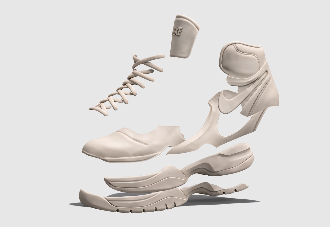
Deterministic seeded ComfyUI workflows. Every run records prompt, seed, model, workflow id and source-asset ids to a LogRun sidecar, and only a designer-approved asset is allowed to feed the next stage — F08 composites the exploded view straight from the F04 layer manifest rather than re-imagining it. The local 8 GB-class GPU develops and validates the workflows; approved cloud and API backends carry the heavy runs.
The instrument
Where it stops being useful.
- Color
- Material
- Component
- Form
- Cross-view consistency
- Downstream handoff
↑ useful exploration breaks here
- EEffective breadth — effective number of idea groups occupied.
- UUseful breadth — distinct groups holding at least one concept the designer would continue developing.
- RRedundancy — concentration of a system's outputs in already repeated idea groups.
- OOntology overflow — outputs that need a new category, or that the current ontology cannot explain.
Two systems generate under one brief. The outputs are mixed, stripped of every source identifier and deterministically randomized into one blind deck of 48–60 cards. Each designer sorts alone — group the cards by what you consider the same design idea, and name the groups only afterwards. Nobody is handed axes. Comparability comes from the shared protocol, not from shared labels.
V0 is instrument validation, not a statistically powered result. A VLM may perform only verifiable classification, validated against human labels — it may not judge novelty, plausibility, quality or taste.
This is the task eval.
Evidence — F08 method comparison, one camera and light rig · The next page reads this same boundary the other way: not as a result, but as the next change to the tool that produced it.
The left loop
A boundary is a work order.
- Color
- Material
- Component
- Form
- Cross-view
- Handoff
↑ breaks here
Not evidence yet. V0 turns the right loop only. The left loop is unproven until a boundary has been converted into a shipped change and re-measured on a brief it was not tuned against — a before/after on the brief that produced the boundary would only be evidence of fitting.
- SymptomLayerThe one change it authorizes
- Colorway holds, material driftsControlsStrengthen the reference adapter; split CMF from geometry.
- A named component will not stay fixedWorkflowRegion lock + masked two-pass. One graph was holding too much.
- Silhouette survives, cross-view identity does notTaskApprove a view set first, then branch from it.
- Every output repeats one ideaSamplingWiden the seeded strata; check the brief for over-specification.
- Output cannot be handed downstreamModelSubstitute a backend whose outputs carry the structure.
One layer at a time. If a model swap and a workflow split ship together, the profile cannot say which one moved the boundary — and a change that cannot be attributed cannot be learned from.
The whole machine
Two loops. One hinge.
I am building two things, and neither improves alone. The tool makes possibilities. The instrument finds where they stop being useful. Each one's output is the other's next input.
The designer is not supplying missing taste to an ignorant machine. The system is making an organization's existing judgment observable, reusable — and then spending it.
A system that measures its own tool can be tuned to its own ruler. So a revised tool re-enters as a new system rather than a new score, it is re-measured on a brief it was not tuned against, and the deck hides revision as well as source.
Buy vs build
Knowing what not to build is the job.
- Photoreal visual directionUse — Vizcom-class tools, Krea, image models. Strong teams already build this. I should not.
- Segmentation · geometry locks · referenceUse — SAM3. Geometry & silhouette protection — ControlNet. Reference — IPAdapter.
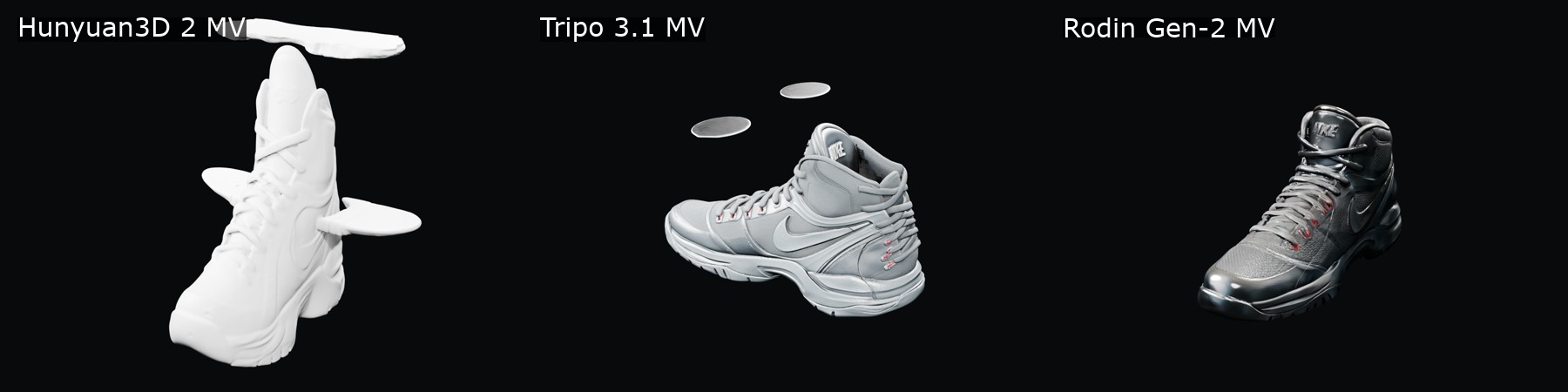
- Early 3D volumeUse — Tripo / Hunyuan / Rodin, whichever passes the task eval. Spatial review, not production CAD.
- Production shoe CADHand off — last, patterns, tooling belong to real footwear CAD. Do not trust generic image-to-3D with them.
- Preserve design state across all of theseBuild — intent, locks, lineage, approvals. Nobody sells the layer that carries a Nike designer's decision through someone else's model.
- Measure where a workflow stops being usefulBuild — the instrument, the boundary, the work order.
- Translate designer feedback into system actionBuild — “too aggressive, keep the tension” → preserve / modify / degree.
Buy the panels. Build the joints.
Every panel is replaceable after passing the task eval — today Vizcom, tomorrow another model. The joints stay: the designer workflow, the design state, and the human decision points.
How it scales
From working prototype to Nike-scale practice.
-
Working now
Today — the prototype
Designer-facing agents → provider adapters → cloud model APIs. This stage validates which design interventions are useful.
-
Scale next
Evaluate and replace
Each specialist agent earns task-specific evaluation criteria. A provider changes only when it passes the relevant evaluation.
-
Nike-scale proposal
Private infrastructure
Designer tools → specialist-agent library → shared model gateway → Nike-hosted open-source or tuned models → internal GPU infrastructure. A path forward — not shipped capability.
Same joints, new panels.
Proven on footwear first. The same contracts can carry apparel colorways, brand assets, retail, motion — the grammar doesn't care what the panel is made of.
Haller proved it in a building before it became furniture.
Build it with designers
Try it on real work → find where intent breaks → translate feedback into the right workflow, model, or UX layer → make the smallest useful change → test again.
Adoption is measured by repeated use and completed creative decisions — not workshop attendance.
- What must stay fixed?
- What may change?
- What does a useful result look like?
- Where must human judgment remain?
Just Build It.
I built the first working version. The next step is to build it with Nike designers — and let the grammar travel.
Independent interview concept prototype; not an official Nike product or internal system.